- Tel:+8613007564317
- Email:[email protected]
News
The main circuit of the series inverter one-to-two medium-frequency electric furnace is composed of the following main parts Three-phase half-controlled rectifier bridge, Rectifier RC absorption circuit, Pre-charging circuit, Current limiting reactor LD, Filter capacitor CL, Series inverter half bridge, Inverter RCD absorption protection circuit, Inductor, L-C tank composed of resonant capacitor, etc. 01 Rectifier trigger excerpt …
The main circuit of the series inverter one-to-two medium-frequency electric furnace is composed of the following main parts
Three-phase half-controlled rectifier bridge,
Rectifier RC absorption circuit,
Pre-charging circuit,
Current limiting reactor LD,
Filter capacitor CL,
Series inverter half bridge,
Inverter RCD absorption protection circuit,
Inductor,
L-C tank composed of resonant capacitor, etc.
01
Rectifier trigger working principle
After the main power is connected, the pre-charging circuit charges the filter capacitor. When the voltage is charged to 500V, the rectifier pulse board collects a negative voltage. After the Hall sensor is transformed, a 10V voltage signal is output and sent to the main board. The main board can start. When the system fails, a negative voltage signal KP is sent to the rectifier pulse board, the rectifier pulse stops, and the DC voltage is cut off.
02
Working principle of regulator
In engineering practice, the most widely used regulator control law is proportional, integral, and differential control, referred to as PID control, also known as PID regulation. It has become one of the main technologies of industrial control due to its simple structure, good stability, reliable operation, and convenient adjustment. When the structure and parameters of the controlled object cannot be fully mastered, or an accurate mathematical model cannot be obtained, and other control theory techniques are difficult to adopt, the system controller structure and parameters must be determined by experience and on-site debugging. At this time, it is most convenient to use PID control technology. That is, when we do not fully understand a system and the controlled object, or cannot obtain system parameters through effective measurement methods, PID control technology is most suitable. PID control, in practice, also has PI and PD control. The PID controller is based on the error of the system, using proportion, integration, and differentiation to calculate the control quantity for control.
Proportional (P) control: Proportional control is the simplest control method. The output of its controller is proportional to the input error signal. When there is only proportional control, there is a steady-state error in the system output.
Integral (I) control: In integral control, the output of the controller is proportional to the integral of the input error signal. For an automatic control system, if there is a steady-state error after entering the steady state, the control system is said to have a steady-state error or a differential system. In order to eliminate the steady-state error, the "integral term" must be introduced in the control term. The integral term depends on the integral of time for the error, and the integral term will increase as time increases. In this way, even if the error is very small, the integral term will increase with time, which drives the controller's output to increase and further reduce the steady-state error until it is equal to zero. Therefore, the proportional + integral (PI) controller can make the system have no steady-state error after entering the steady state.
Control system regulators include: voltage regulators, current regulators, etc.
03
Basic working principle of the main circuit
UL 380V-660V The incoming line voltage is rectified and outputs a DC voltage. After filtering by the reactor and the filter capacitor, a stable DC voltage UD (constant voltage source) is formed. The DC voltage passes through the inverter bridge and the resonant capacitors C1, C2 and the induction coil L to form an oscillation to heat the metal material in the furnace body.
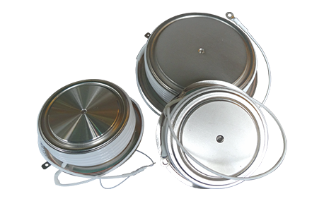
Inverter thyristor protection: The protection of inverter thyristor is mainly to suppress di/dt and dv/dt during the commutation process. The commutation inductor Lk is used to suppress the current change rate di/dt, and the composite RCD absorption circuit is used to suppress the voltage change rate dv/dt.
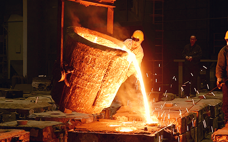
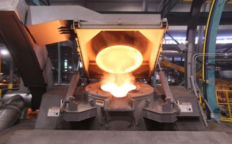
In the forging workshop, industrial furnaces smelt metals, including cupola, induction furnace, resistance furnace, electric arc furnace, vacuum furnace, open hearth furnace, crucible furnace, etc; There are sand mold drying furnace for baking sand mold, ferroalloy drying furnace and casting annealing furnace, etc; In the forging workshop, there are various heating furnaces for heating ingots or billets before forging and heat treatment furnaces for relieving stress after forging;
The most effective way for the failure of the medium frequency furnace is to use the low current experiment to judge whether it is the fault of the rectifier circuit or the fault of the inverter part. In the low current experiment, when the DC voltage is less than 513v, it indicates that there is a phase loss fault in the DC rectifier part. Check the specific thyristor fault, and the pulse breaking method should be used to judge whether it is the thyristor fault or there is no trigger pulse.
The most effective method for the failure of the intermediate frequency furnace is to use a small current experiment to judge whether the rectifier circuit is faulty or part of the inverter fault. When the DC current is less than 513 volts
Please send us your request and we will reply to you within 24 hours.
We will get in touch with you as soon as possible